As businesses expand their surveillance systems, managing network traffic becomes increasingly important. A CCTV installation with eight cameras may work well on a simple network, but a warehouse, shopping mall, industrial facility, or campus with 64, 100, or 200 cameras needs a carefully planned network backbone. Without sufficient capacity, the system may experience video delays, interrupted streams, and unreliable playback.
WeFour Connect provides professional fiber optic installation and splicing, CCTV installation, structured cabling, and network infrastructure services in Doha, Qatar. We help businesses design reliable surveillance networks with the capacity, connectivity, and scalability required for large camera installations.
If you are planning a new CCTV system or upgrading an existing one, understanding why fiber optic cabling is an effective backbone solution can help you make a more informed investment.
What Is a CCTV Network Backbone?
A CCTV network backbone is the high-capacity network infrastructure connecting camera switches, network cabinets, server rooms, and video recorders.
In a typical IP CCTV system, cameras connect to local network switches using Ethernet cables. These switches then transmit video traffic through backbone links to the central network and recording equipment.
Think of the backbone as a motorway connecting different parts of a city. Individual camera connections are smaller roads, while the backbone carries traffic from multiple areas. If the motorway becomes congested, the entire system can suffer.
For large CCTV installations, a properly designed backbone helps ensure that video streams reach the recording system reliably, even when many cameras are operating simultaneously.
Why Do Large CCTV Systems Need More Network Capacity?
Every IP camera generates video traffic. The amount depends on resolution, frame rate, compression, image complexity, and camera configuration.
Consider a site with 64 IP cameras:
- At an average bitrate of 4 Mbps per camera, the combined video traffic is approximately 256 Mbps.
- At an average bitrate of 8 Mbps per camera, the combined traffic is approximately 512 Mbps.
These figures represent the combined camera streams before allowing for additional traffic such as live viewing, playback, network overhead, and other business applications.
A gigabit Ethernet link may handle many installations successfully, but the correct design must account for peak traffic, uplink aggregation, equipment capacity, and future growth. Larger systems may benefit from multi-gigabit or 10-gigabit backbone links, depending on their requirements.
This is where fiber optic cabling becomes particularly useful.
7 Reasons Fiber Optic Cabling Is Ideal for Large CCTV Systems
1. Higher Bandwidth for Multiple Camera Streams
Fiber optic links can support high bandwidth over suitable distances. Depending on the fiber type and optical equipment, they can accommodate gigabit, 10-gigabit, and higher-speed connections.
This makes fiber a strong option for connecting multiple camera switches to a central recording room.
For example, a large warehouse may have several groups of cameras connected to local switches. Fiber uplinks can carry their combined traffic back to the central network without requiring a separate long copper cable for every camera.
Business benefit: A properly sized fiber backbone provides greater capacity for current camera traffic and future upgrades.
2. Longer Transmission Distances
Standard Ethernet over balanced copper cabling generally supports channel lengths of up to 100 metres, subject to the applicable standard and installation conditions.
Large properties often require connections beyond this distance, including links between buildings, distant network cabinets, parking areas, and industrial zones.
Fiber optic cabling can carry data over much longer distances. The supported distance depends on the fiber type, optical transceivers, data rate, and link budget.
Single-mode fiber is commonly used for long-distance connections, while multimode fiber may suit shorter links within buildings or facilities.
Business benefit: Fiber makes it easier to connect distant camera zones without exceeding the practical limits of standard copper Ethernet cabling.
3. Immunity to Electromagnetic Interference
Copper network cables transmit electrical signals and can be affected by electromagnetic interference in certain environments.
Fiber optic cables transmit data using light, so the fiber itself is not susceptible to electromagnetic interference.
This is particularly useful in industrial facilities, factories, plant rooms, and other locations containing motors, generators, lifts, or heavy electrical equipment.
Business benefit: Fiber helps maintain reliable data transmission in electrically noisy environments when correctly installed and terminated.
4. Safer Connections Between Buildings
Copper cabling between separate buildings can create electrical bonding and surge-related concerns, particularly where different grounding conditions exist.
Because the optical fiber itself is non-conductive, a fiber link provides electrical isolation between connected locations. This can reduce certain risks associated with conductive data cabling between buildings.
However, the complete installation still requires suitable protection for powered equipment, cable infrastructure, and any conductive components.
Business benefit: Fiber is often a preferred option for connecting CCTV networks across separate buildings, campuses, and outdoor facilities.
5. Simplified Cabling for Distributed Camera Networks
Pulling individual copper cables over long distances from every camera to one central room can create complicated cable routes and crowded trays.
A distributed design can be more practical:
- Install local network cabinets near groups of cameras.
- Connect nearby IP cameras to PoE switches using copper Ethernet.
- Connect each local switch to the central network using fiber.
- Consolidate camera traffic at the central switch and recording system.
This arrangement reduces the need for long individual copper runs and can make the overall network easier to organize and maintain.
Business benefit: A structured fiber backbone can simplify large installations and make future changes easier to manage.
6. Improved Electrical Isolation and Network Security Options
Fiber does not conduct electricity through its optical transmission path and does not radiate electrical signals in the same way as copper data cabling.
This provides electrical isolation and can make certain forms of physical signal interception more difficult. However, fiber is not completely immune to tapping or tampering, and the security of a CCTV system also depends on network configuration, access controls, encryption, and physical protection.
Business benefit: Fiber can contribute to a more robust network design when combined with appropriate cybersecurity and physical security measures.
7. Easier Expansion for Future CCTV Upgrades
Businesses often add cameras when they expand buildings, install new equipment, or introduce additional security requirements.
A fiber backbone with sufficient spare capacity can support future network upgrades without requiring every backbone cable to be replaced. In many cases, faster optical equipment can be installed at the endpoints, provided the existing fiber and other components support the intended speed and distance.
For example, a business may initially operate a 1-gigabit uplink and later upgrade selected connections to 10 gigabits using compatible equipment.
Business benefit: Planning fiber infrastructure for future growth can reduce the need for costly cabling changes later.
Fiber vs. Copper for CCTV Systems
Fiber and copper both have important roles in IP CCTV installations. The best solution often combines the two rather than replacing every copper cable with fiber.
| Feature | Fiber optic cabling | Copper Ethernet |
| Transmission distance | Suitable for longer links, depending on equipment | Typically up to 100 m per standard Ethernet channel |
| Bandwidth | Supports high-speed backbone connections | Supports a wide range of Ethernet speeds |
| Electrical interference | Immune along the optical fiber | Susceptibility depends on cable type and environment |
| Power delivery | Does not deliver PoE through the fiber itself | Can deliver PoE to compatible cameras |
| Typical CCTV use | Backbone links between switches and buildings | Connections from switches to nearby cameras |
| Installation considerations | Requires compatible optical equipment and careful handling | Often simpler for short camera connections |
For most large IP CCTV systems, fiber is particularly valuable for backbone connectivity, while copper remains practical for the final connection to individual cameras.
How Fiber and PoE Work Together in a CCTV Network
One important point to understand is that fiber optic cabling carries data but does not directly power standard IP cameras through Power over Ethernet (PoE).
A typical fiber-backed CCTV design works as follows:
- IP cameras connect to a nearby PoE network switch using copper Ethernet cables.
- The PoE switch supplies power to compatible cameras and collects their video traffic.
- A fiber uplink connects the local switch to the central network.
- The central switch forwards video traffic to the NVR or video management server.
- Recording equipment stores the footage for later playback and investigation.
If a camera is located far from a convenient power source, the design may require a remote powered switch, local power supply, or other suitable equipment.
The correct arrangement depends on cable distances, available power, environmental conditions, and maintenance access.
What Does a Fiber-Backed CCTV Network Look Like?
Consider a warehouse with cameras installed across the storage area, loading bays, perimeter, and office building.
A suitable design could include:
- Central equipment room: Houses the core network switch, NVRs or video management servers, and storage equipment.
- Local network cabinets: Connect groups of cameras through PoE switches positioned near their coverage areas.
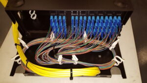
- Fiber backbone links: Connect local cabinets to the central equipment room.
- Copper camera connections: Connect each camera to the nearest suitable PoE switch.
- Redundant links where required: Provide an alternative path for critical connections if the network design and budget support it.
- Clear labeling and documentation: Make network troubleshooting, maintenance, and future upgrades easier.
For critical sites, redundancy may include separate fiber routes, ring topologies, or dual uplinks. Redundancy must be designed carefully: two links sharing the same physical route may still fail together if that route is damaged.
Single-Mode vs. Multimode Fiber for CCTV
Choosing the correct fiber type depends on transmission distance, network speed, equipment compatibility, and budget.
Single-Mode Fiber
Single-mode fiber is commonly used for long-distance connections between buildings, remote network cabinets, and large industrial or campus installations.
It supports a wide range of optical transmission options and is often a practical choice for new backbone installations where future expansion is important.
Multimode Fiber
Multimode fiber is often used for shorter-distance connections within buildings, equipment rooms, and facilities where compatible optical equipment is already in place.
Its supported distance depends on the fiber grade, data rate, and optical transceivers.
Which Should You Choose?
For new installations that may need longer links or future upgrades, single-mode fiber is often worth considering. However, the correct choice should be based on a site survey, transmission distances, network speeds, available equipment, and project costs.
Common Mistakes to Avoid When Planning a CCTV Fiber Backbone
Even good-quality fiber can underperform if the overall network is poorly designed.
1. Underestimating Network Traffic
Calculate expected traffic from all cameras and allow headroom for peak activity, live viewing, playback, and future additions.
2. Using a Single Overloaded Uplink
Combining too many camera streams on an undersized connection can create congestion. Select uplink speeds according to the expected load and the capacity of the switches and recording system.
3. Ignoring Camera Power Requirements
Fiber does not provide PoE directly. Plan the location and power supply of every local switch, especially in outdoor areas and remote buildings.
4. Poor Fiber Termination or Splicing
Poor-quality splices, dirty connectors, excessive bends, and incorrect handling can introduce optical loss.
Use qualified technicians and request appropriate test results, such as optical loss measurements, at handover.
5. Failing to Plan Redundancy
If a single fiber link serves an entire building, damage to that link may disconnect all cameras in the affected area. Evaluate whether critical zones need alternative routes or redundant connections.
6. Neglecting Documentation
Label fiber cables, patch panels, switch ports, and network cabinets. Maintain clear diagrams showing where each link terminates.
7. Forgetting Future Expansion
Consider future cameras, higher resolutions, increased recording requirements, and additional network services when sizing the backbone.
CCTV Fiber Backbone Planning Checklist
Before installing or upgrading a large CCTV system, review these points:
- Count the current cameras and estimate future expansion.
- Calculate the expected video traffic using realistic camera bitrates.
- Include bandwidth for playback, monitoring, and other network services.
- Measure the distances between cameras, switches, buildings, and the central room.
- Select suitable fiber types, optical transceivers, and uplink speeds.
- Plan PoE switch locations and power availability.
- Assess whether redundant links or separate cable routes are required.
- Protect cables against environmental and physical damage.
- Test fiber links and document the results.
- Label and document all network connections.
- Schedule regular inspection and maintenance.
A well-planned backbone helps businesses avoid unnecessary rework and maintain reliable video transmission as their surveillance systems grow.
How WeFour Connect Can Help With CCTV Fiber Optic Installation in Doha
Large CCTV systems perform best when camera placement, network switches, fiber links, power, and recording equipment are planned together.
WeFour Connect provides CCTV and network infrastructure services in Doha, Qatar, helping businesses develop surveillance networks suited to their sites and operational requirements.
Our services include:
- Fiber optic installation and splicing: Backbone connections between network cabinets, buildings, and central equipment rooms.
- Professional CCTV installation: Surveillance systems designed around site layout and monitoring requirements.
- Structured cabling: Organized cabling infrastructure for cameras, switches, and other network equipment.
- Customized network design: Solutions based on camera count, transmission distances, capacity requirements, and future expansion.
- Warranty and Annual Maintenance Contracts (AMC): Support and maintenance options for network and surveillance infrastructure.
- Support for critical issues: Assistance according to the applicable service arrangements.
Smaller jobs may take a few hours, while larger installations can take several days or longer depending on cable routes, site access, equipment requirements, and project scope.
Contact WeFour Connect to discuss your CCTV network and explore a fiber backbone solution for your premises.
WeFour Connect — Doha, Qatar
- Address: Office No. 5, Bank Street, West Bay, Doha, Qatar
- Phone: +974 3146 4818 | +974 3146 4718
- Email: info@wefourconnect.com